Support positions, load cases, fixings and joint details were not supplied. The following examples are created for comparison; they do not establish that any completed job or proposed installation is safe.
For vertical faces, a bottom ledger can carry gravity while separate restraints resist out-of-plane movement. A framed backing system is another option.
Verify panel orientation, substrate, anchors, eccentricity, movement and any appliance heat clearances.
Component load diagrams
Each outline has its own drawing. Open a component to see its forces, assumed supports and worked calculations.
Results are per physical piece; quantities are shown separately. Alternative drawing sheets are not added together. Horizontal surface examples add an illustrative 500 N point load to stone self-weight; trim strips and vertical panels use self-weight only.
Gross dimensions remain unverified drawing readings. Assumed 20 mm thicknesses and proxy densities are identified in every worked record. These scenario inputs do not replace the fixed measurement tables.
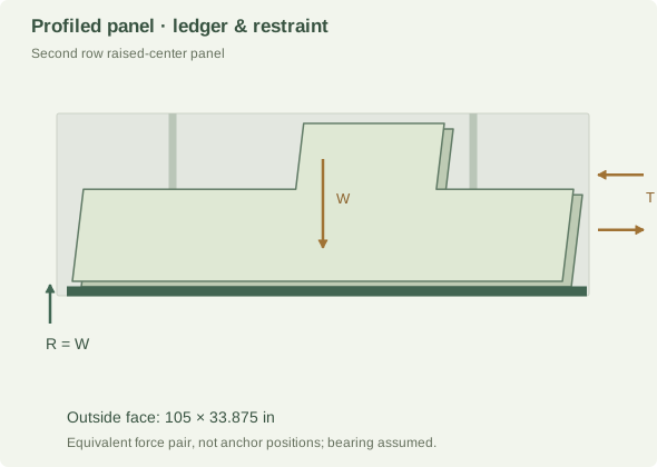
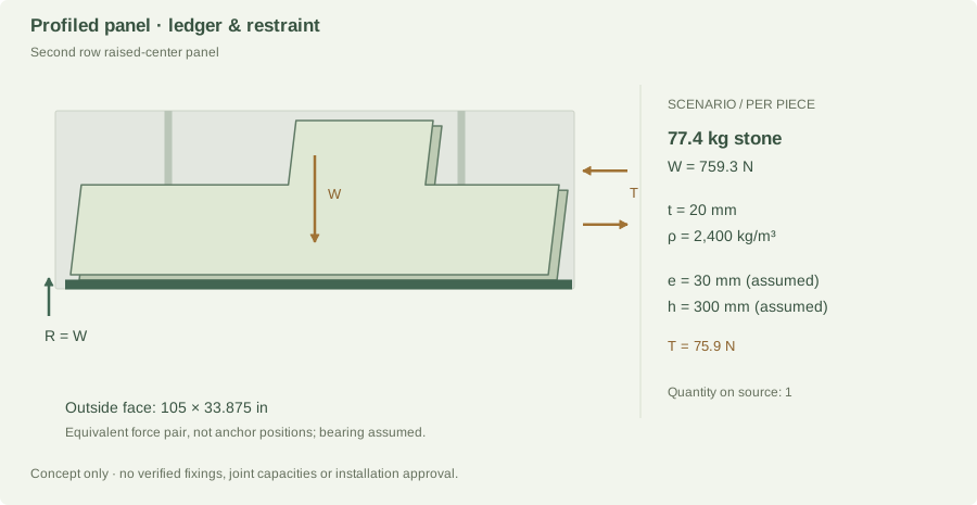
Second row raised-center panel Panel load path · per piece
Gross outline from project-7.jpg; support layout and orientation are scenario assumptions. Image shows one piece; source quantity is 1. Fixture openings are not reconstructed in this gross-outline model.
Gross area 1.6124 m²; thickness 20 mm (drawing reading); density 2,400 kg/m³ (Estimate · historical TCE family range). Openings are not deducted; cutout stress concentrations and remaining stone strips need a separate check.
m = A × t × ρ = 1.6124 × 0.020 × 2,400 = 77.40 kg
W = m × 9.81 = 759.26 N
Lower bearing demand R = W = 759.3 N Assumed offset e = 0.030 m; restraint separation h = 0.3000 m M = W × e = 22.78 N·m T = M ÷ h = 75.93 N
The assumed separation is the smaller of 300 mm and 60% of the panel’s short outside dimension. This keeps the example couple within its outline; it does not establish anchor placement or edge clearances. The forces form an idealized upper-restraint/lower-bearing couple for one panel. They are not individual anchor capacities. Anchor prying, shared load, substrate strength and lateral/seismic loads are unassigned.
Joint demand and support strength
The bottom joint or ledger must transfer at least the 759.3 N modeled gravity demand from this panel, plus other applicable design actions. Adhesive-only suspension is not assumed.
Capacity pending: stone bending and deflection, local bearing, support stiffness, joint shear/peel, connection capacity, load factors and the final design load combinations are not established. A bond area or an adhesive coupon strength alone cannot establish the installed joint’s capacity.
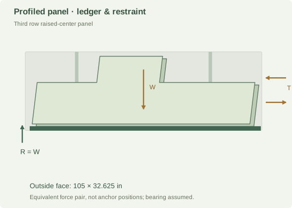
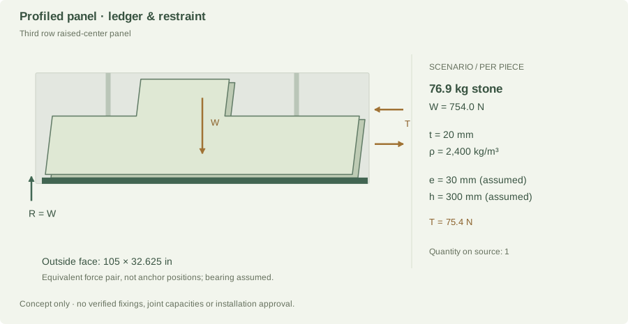
Third row raised-center panel Panel load path · per piece
Gross outline from project-7.jpg; support layout and orientation are scenario assumptions. Image shows one piece; source quantity is 1. Fixture openings are not reconstructed in this gross-outline model.
Gross area 1.6012 m²; thickness 20 mm (drawing reading); density 2,400 kg/m³ (Estimate · historical TCE family range). Openings are not deducted; cutout stress concentrations and remaining stone strips need a separate check.
m = A × t × ρ = 1.6012 × 0.020 × 2,400 = 76.86 kg
W = m × 9.81 = 753.99 N
Lower bearing demand R = W = 754.0 N Assumed offset e = 0.030 m; restraint separation h = 0.3000 m M = W × e = 22.62 N·m T = M ÷ h = 75.40 N
The assumed separation is the smaller of 300 mm and 60% of the panel’s short outside dimension. This keeps the example couple within its outline; it does not establish anchor placement or edge clearances. The forces form an idealized upper-restraint/lower-bearing couple for one panel. They are not individual anchor capacities. Anchor prying, shared load, substrate strength and lateral/seismic loads are unassigned.
Joint demand and support strength
The bottom joint or ledger must transfer at least the 754.0 N modeled gravity demand from this panel, plus other applicable design actions. Adhesive-only suspension is not assumed.
Capacity pending: stone bending and deflection, local bearing, support stiffness, joint shear/peel, connection capacity, load factors and the final design load combinations are not established. A bond area or an adhesive coupon strength alone cannot establish the installed joint’s capacity.
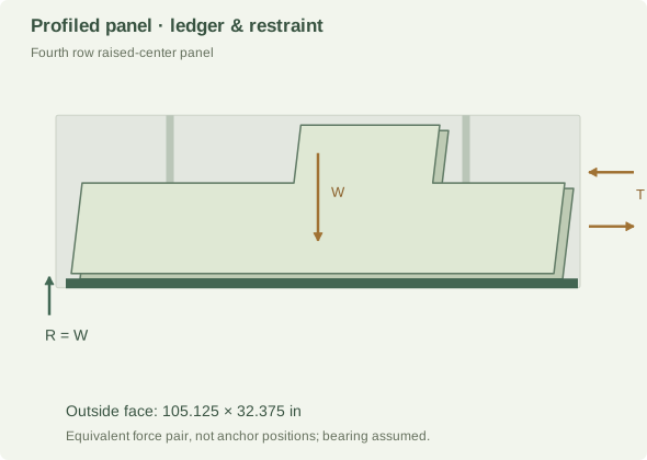
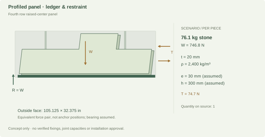
Fourth row raised-center panel Panel load path · per piece
Gross outline from project-7.jpg; support layout and orientation are scenario assumptions. Image shows one piece; source quantity is 1. Fixture openings are not reconstructed in this gross-outline model.
Gross area 1.5859 m²; thickness 20 mm (drawing reading); density 2,400 kg/m³ (Estimate · historical TCE family range). Openings are not deducted; cutout stress concentrations and remaining stone strips need a separate check.
m = A × t × ρ = 1.5859 × 0.020 × 2,400 = 76.12 kg
W = m × 9.81 = 746.76 N
Lower bearing demand R = W = 746.8 N Assumed offset e = 0.030 m; restraint separation h = 0.3000 m M = W × e = 22.40 N·m T = M ÷ h = 74.68 N
The assumed separation is the smaller of 300 mm and 60% of the panel’s short outside dimension. This keeps the example couple within its outline; it does not establish anchor placement or edge clearances. The forces form an idealized upper-restraint/lower-bearing couple for one panel. They are not individual anchor capacities. Anchor prying, shared load, substrate strength and lateral/seismic loads are unassigned.
Joint demand and support strength
The bottom joint or ledger must transfer at least the 746.8 N modeled gravity demand from this panel, plus other applicable design actions. Adhesive-only suspension is not assumed.
Capacity pending: stone bending and deflection, local bearing, support stiffness, joint shear/peel, connection capacity, load factors and the final design load combinations are not established. A bond area or an adhesive coupon strength alone cannot establish the installed joint’s capacity.
A real bracket, in a separate example bay.
This example uses TCE1220 at 20 mm and 2,400 kg/m³. It does not claim this overhang exists in Project 07. A 350 mm overhang, 400 mm tributary width and 500 N tip load are deliberately assumed.
Calculated load demands
W_bay = ρ × t × 0.400 × 0.350 × 9.81 = 65.92 N
V = W_bay + 500 = 565.92 N
M_root = W_bay × 0.350/2 + 500 × 0.350
= 186.54 N·m
For a separate ideal connection with h = 0.150 m:
T_couple = M_root ÷ h = 1,243.58 N
The 150 mm force-couple lever arm is an algebra example for a vertically separated connection. It is not the Liberty’s flush-mounted lag-screw geometry or an anchor specification.
Federal Brace Liberty · SKU 30247
Published carry reference: 375 lbf per bracket ≈ 1,668 N. The bracket has a 12 in support projection plus 4⅛ in mounting length, with a 3 in width and ¼ in steel thickness.
Its guide calls for double 2×4 knee-wall blocking tied into the floor, flush/level mounting and spacing no greater than 18 in (457 mm). The 400 mm example bay is within that spacing figure. The assumed 350 mm overhang extends about 45 mm beyond the 305 mm arm; permissible stone extension still needs confirmation.
Comparison, not approval: the calculated 566 N shear is 33.9% of the catalog force reference. The guide does not establish the actual anchor-group moment resistance, stone capacity, test load position or an applicable design safety factor. Those checks remain open.
A real concealed cabinet-sidewall option. Current guidance discusses 16–20 in support spacing and material-thickness-dependent reach. A published 500 lb test claim does not state a verified per-bracket basis, so no numeric capacity is assigned here.
A separate cabinet-supported sink cradle can keep sink and water loads off an adhesive seam. The manufacturer’s telescoping rail range is 25–47 in; no numeric capacity was verified. Confirm cabinet clear width, sink weight, contained water and rail capacity.
Prefer a defined bearing path below a seam. An unsupported miter can carry shear, bending and peel; average shear alone is insufficient. The adhesive, substrate, bond geometry, cure, durability and design resistance must match the actual joint.
For example, 3M DP420 Black publishes a 17 MPa aluminum lap-shear test after seven days at 23°C. That is not a stone-to-stone seam allowable, so it is not used to size these joints.
Measure actual support lines, unsupported spans, overhangs, contact widths and seam positions.
Confirm stone thickness, identity, density, cutout shape/radii and product-specific fabrication guidance.
Establish applicable service, concentrated, impact, lateral/seismic and installation load cases and design factors.
Verify frame/bracket stiffness, local bearing, cabinet and floor load paths, blocking, fasteners and anchorage.
Obtain matched joint data for shear, peel, bending, cure and durability; confirm movement and appliance clearances.
Have the final arrangement checked by the fabricator and a qualified structural professional where needed.
Required resistance must cover the governing design demand on a consistent load/resistance basis. These pages calculate selected service-load demands; they do not supply tested allowable capacities or a code-compliant design factor. Stone cracking, deflection and joint failure therefore remain unresolved.
Sources, scope and calculation record
Force balance and moments use algebra: ΣF = 0 and ΣM = 0. No calculus is required for these demand examples.
TCE Stone Quartz products in Canada; no thickness-specific support schedule. No verified TCE numeric overhang, bracket-spacing or wall-anchor guidance was found in public resources. Request current regional installation instructions; do not transplant another brand table.
Manufacturer tables apply only within their stated products, thicknesses, regions and installation conditions. They are not copied into a universal allowable-span rule. Research checked 24 October 2026.